Identix CONNECTIX - Quick Start Guide for Identix RAIN RFID readers and IoT gateways V1.0
For all devices based on Identix SAMx00 modules, hardware V1 and V2.
Introduction
Section titled “Introduction”Identix IoT RFID readers and gateways are built on CONNECTIX OS, an embedded operating system with an optimized protocol stack for real-time acquisition, processing and transmission of RAIN RFID data to enterprise applications and cloud platforms.
CONNECTIX OS provides a unified software architecture with a consistent API layer across all supported devices. It exposes hardware-specific features and low-level controls through a dedicated firmware abstraction layer.
Initial setup
Section titled “Initial setup”Connect the device to a power supply
Section titled “Connect the device to a power supply”Different models of Identix readers are powered by USB, PoE or DC. Connect the device to the appropriate power source before you configure it.
The power supply must meet the energy demand of the equipment. An inadequate power supply can cause communication failures, restarts, and even permanent damage to the equipment.
Consult the manual for each piece of equipment to confirm that it works correctly.
Warning: Identix gateways comply with the USB 2.0 standard and use +5 V DC for power.
Access the embedded Wi-Fi hotspot
Section titled “Access the embedded Wi-Fi hotspot”When the gateway powers up, it creates a Wi-Fi hotspot automatically. The network SSID follows the format <Model> <last three octets of the WLAN MAC address>. For example: EZ500-LT 51:2B:50.
The internal Wi-Fi hotspot is intended only for initial device configuration. It is not designed for continuous operation. For normal use, connect the gateway to a stable, permanent Wi-Fi network.
Use the following password to connect to the gateway hotspot: !Idntx1234
Log into the administration console
Section titled “Log into the administration console”After you connect to the gateway Wi-Fi hotspot, open a browser at the default IP address, http://192.168.4.1, to access the administration console.
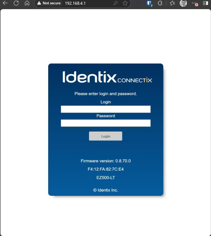
When the login screen appears, use the default credentials:
- Default login: identix
- Default password: identix
Both are in lowercase.
After you log in, you can view and change all gateway configuration parameters in the administration console.
Network configuration
Section titled “Network configuration”Depending on the model, gateways connect to the user’s network through Wi-Fi (WLAN client mode) or Ethernet. They send collected data to business applications and cloud platforms through standard protocols such as MQTT, HTTP or sockets.
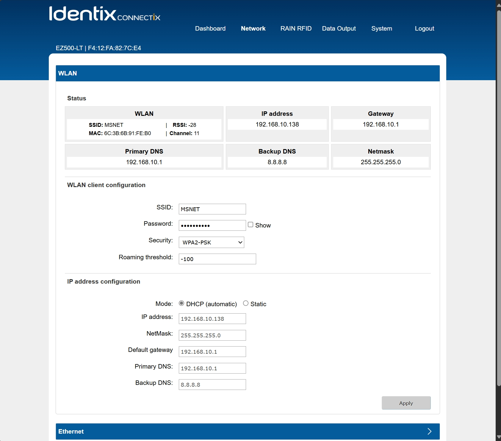
The integrated RAIN RFID reader can also communicate directly with a host computer through the USB interface, if required.
Use the sections below to configure IP settings for Ethernet, Wi-Fi, or both.
Enter the SSID of the Wi-Fi network the gateway should join. If the device will operate only through USB, leave the SSID field blank to disable Wi-Fi.
The network troubleshooting screen tests the equipment’s connectivity to a given host.
Main dashboard
Section titled “Main dashboard”The system dashboard shows key information: network status, firmware and hardware versions, RFID inventory state, the configured operating region, and overall system status.
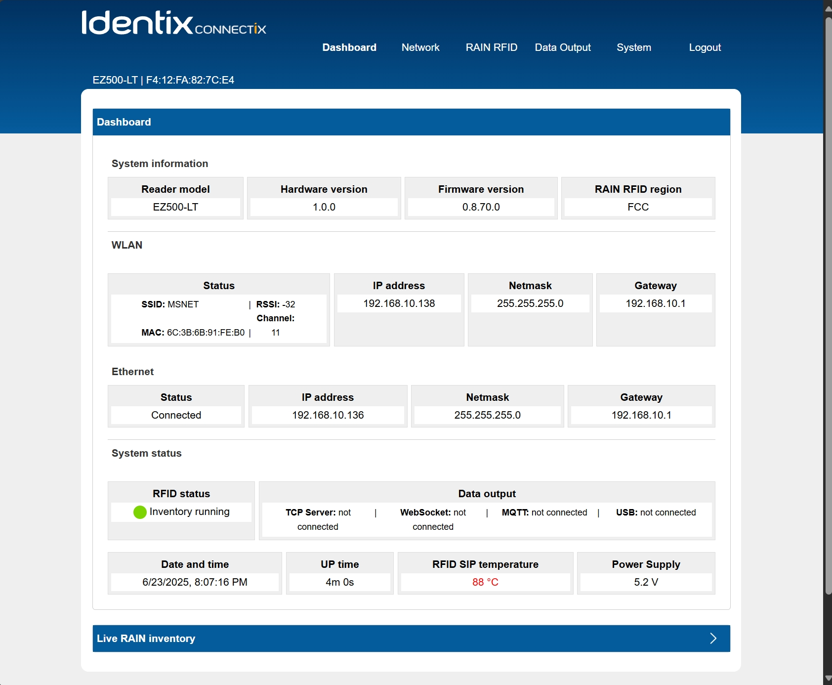
Network status
Section titled “Network status”This section summarizes the Ethernet and Wi-Fi connection status.
Live RAIN RFID inventory
Section titled “Live RAIN RFID inventory”This panel shows real-time RAIN RFID inventory data. The interface uses WebSocket communication. Click Connect to start live data streaming.
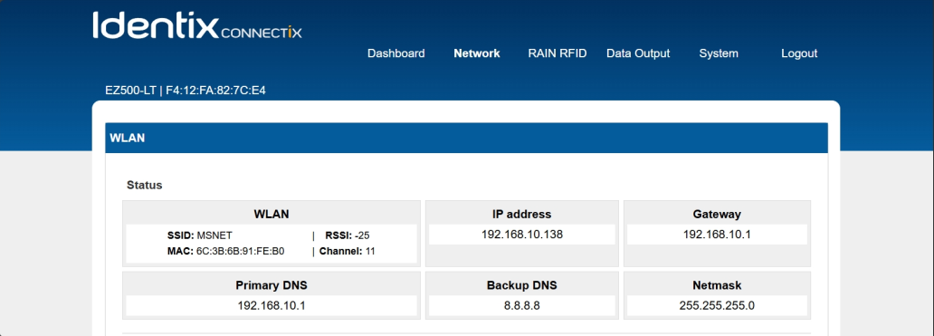
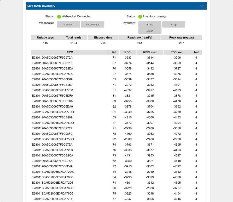
The panel also shows additional metrics, such as the unique tag count, elapsed time, and read rates.
RAIN RFID reader configuration
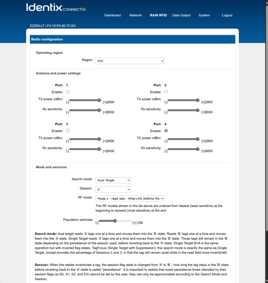
Section titled “RAIN RFID reader configuration”This section configures the operating parameters of the RAIN RFID reader.
Region
Section titled “Region”Select the operating region for the reader. The default is FCC.
Antenna and power settings
Section titled “Antenna and power settings”Enable or disable each antenna port, and adjust the transmit power and read RSSI levels.
Search mode, sessions and RF mode
Section titled “Search mode, sessions and RF mode”The radio configuration section sets the RAIN RFID search mode, session parameters, and RF operating mode.
Search mode
- Dual Target: Alternates between reading A and B tags. After a read, A tags move to the B state, and B tags return to the A state.
- Single Target: Reads A tags and moves them to the B state, where they stay for the session persistence time before they return to A.
- Single Target B>A: Same as Single Target, with inverted flag behavior.
- TagFocus (Single Target with suppression): Works like Single Target, but with Sessions 2 and 3. Tags stay silent (suppressed) while they remain in the read field after being inventoried, which reduces redundant reads.
Session
When a tag is inventoried, its session flag changes from A to B. The time a tag stays in the B state before it returns to A is called persistence. Persistence depends on the selected search mode and session (S0, S1, S2 or S3). The exact persistence times are set by the hardware and cannot be configured by the user.
RF mode
The RF mode defines the modulation scheme, timing, and data rate. Lower data rates give higher sensitivity and better resistance to RF interference. Higher data rates give faster communication, but they are more affected by interference. The RF modes are listed from highest to lowest data rate, which is also the order from lowest to highest sensitivity.
Population estimate
Section titled “Population estimate”The population estimate is an internal parameter. The reader uses it to approximate the number of tags in the read zone during inventory.
The reader uses this estimate to adjust the anti-collision algorithm and inventory timing, which keeps reads reliable and efficient. A correct estimate lets the reader:
- Adjust the number of slots in the anti-collision process to reduce collisions.
- Balance reading speed and reliability.
- Read accurately in environments with large or dense tag populations.
- Respond faster by avoiding unnecessary inventory cycles.
In most cases, the reader calculates the population estimate in real time. In controlled environments with a known, fixed tag population, adjusting it manually can further improve reading efficiency.
Inventory
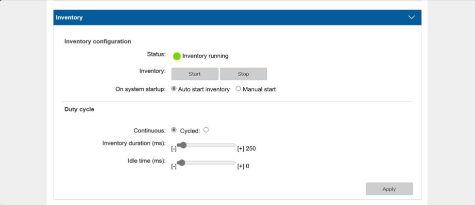
Section titled “Inventory”Inventory configuration sets how the reader starts inventory after the system starts.
Duty cycle sets whether inventory runs continuously or in cycles, to reduce power consumption.
Output data formatting, GS1 EPC decoding and heartbeat
Section titled “Output data formatting, GS1 EPC decoding and heartbeat”JSON fields. By default, tag data is sent in JSON format, and the EPC field is always included. You can also enable these fields:
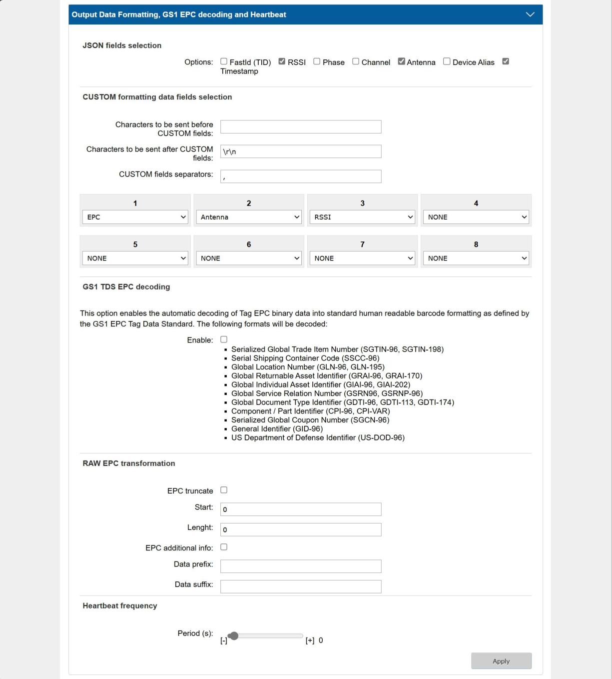
- FastID: Quickly reads the unique chip serial number (TID) of supported Impinj tags, without extra commands.
- RSSI: Received signal strength indicator. It shows the strength of the signal from the tag, which helps estimate distance or signal quality.
- Phase: The phase difference between the transmitted and reflected signal. It is used for location and movement detection.
- Channel: The frequency channel on which the tag was read.
- Antenna: The antenna port that read the tag.
- Device alias: A user-defined name to identify the reader.
- Timestamp: The UTC time of the read event, in milliseconds.
Custom format. You can send data in a custom format, with full control over the order of the fields and the characters used to format and separate them.
GS1 TDS EPC decoding. When enabled, the reader converts EPC binary data into standard, readable formats based on the GS1 EPC Tag Data Standard. It decodes these formats:
- Serialized Global Trade Item Number (SGTIN-96, SGTIN-198)
- Serial Shipping Container Code (SSCC-96)
- Global Location Number (GLN-96, GLN-195)
- Global Returnable Asset Identifier (GRAI-96, GRAI-170)
- Global Individual Asset Identifier (GIAI-96, GIAI-202)
- Global Service Relation Number (GSRN-96, GSRNP-96)
- Global Document Type Identifier (GDTI-96, GDTI-113, GDTI-174)
- Component / Part Identifier (CPI-96, CPI-VAR)
- Serialized Global Coupon Number (SGCN-96)
- General Identifier (GID-96)
- US Department of Defense Identifier (US-DOD-96)
RAW ECP transformation
Section titled “RAW ECP transformation”- EPC truncate: Cuts the ECP data from a given position.
- EPC additional info: Adds strings to the beginning or end of the EPC data.
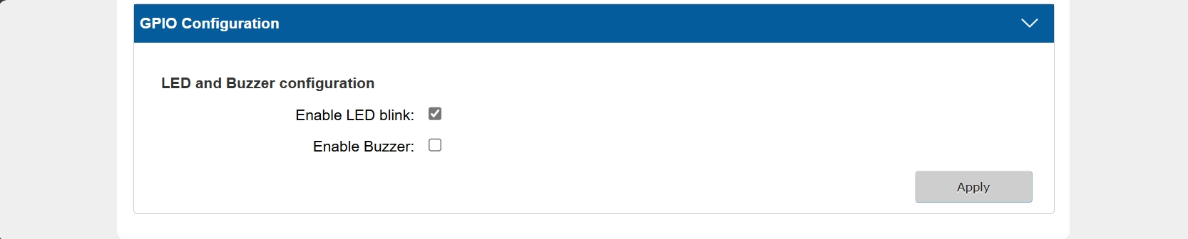
LED and buzzer sets how the LED and buzzer behave during inventory.
Data output
Section titled “Data output”This section sets how collected data reaches applications and services. JSON data can be sent through several channels, including USB, MQTT brokers, and other supported interfaces.
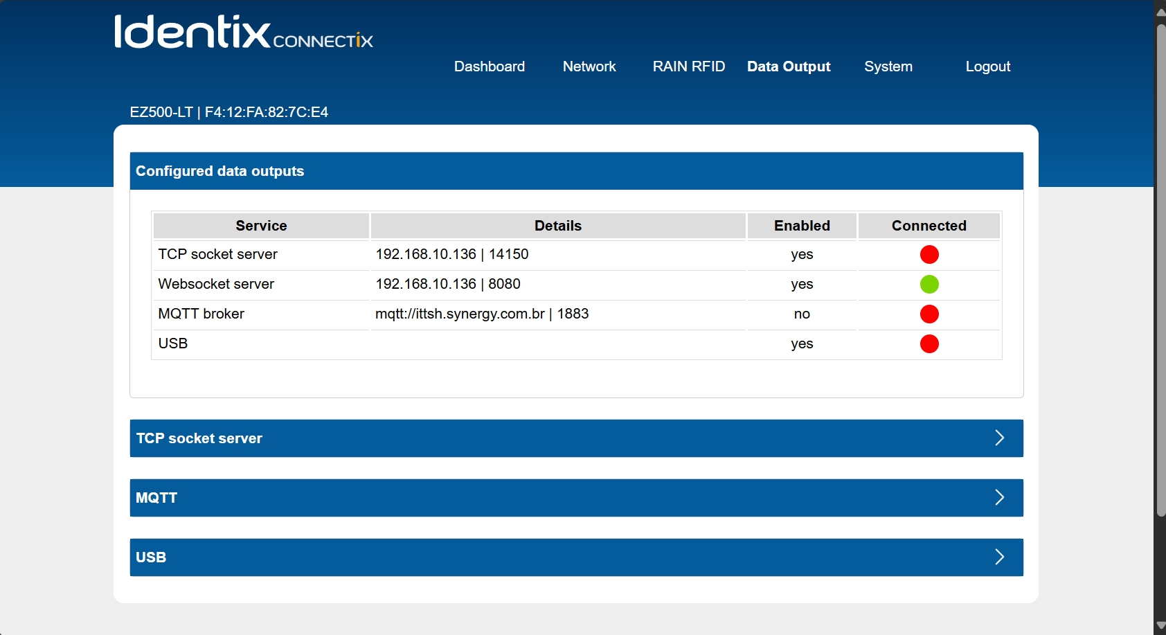
Configured data outputs shows each configured output and its connection status.
TCP socket server
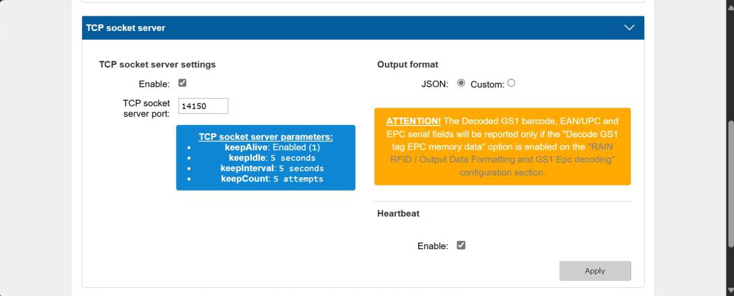
Section titled “TCP socket server”When enabled, the reader starts a socket server. The application connects to the TCP port set in this section to read the data. You can select JSON or custom format, and enable the periodic heartbeat message, which shows the reader’s operating status.
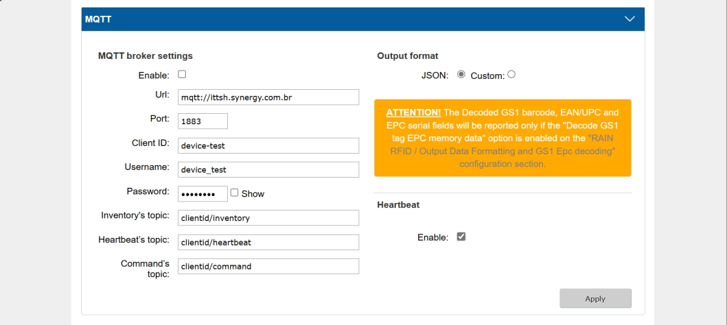
The reader can send data to a designated MQTT broker. Set the broker address and the publication topics here. You can select JSON or custom format, and enable the periodic heartbeat message.
This section configures the USB port. The USB port is disabled by default. To use it, enable it and select an operating mode. You can also choose JSON or custom format, and enable the heartbeat signal.
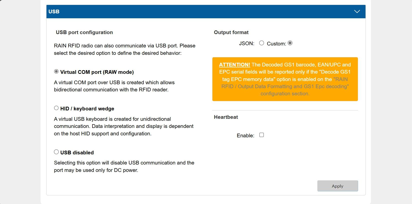
Available USB operating modes:
- Virtual COM port: The USB port works as a virtual serial (COM) port for data transmission.
- HID / keyboard wedge: The USB port acts as a keyboard and sends data as keystrokes.
- USB disabled (default): RFID data is not sent over USB. A virtual COM port is created for system debugging only.
System information and management
Section titled “System information and management”System information
Section titled “System information”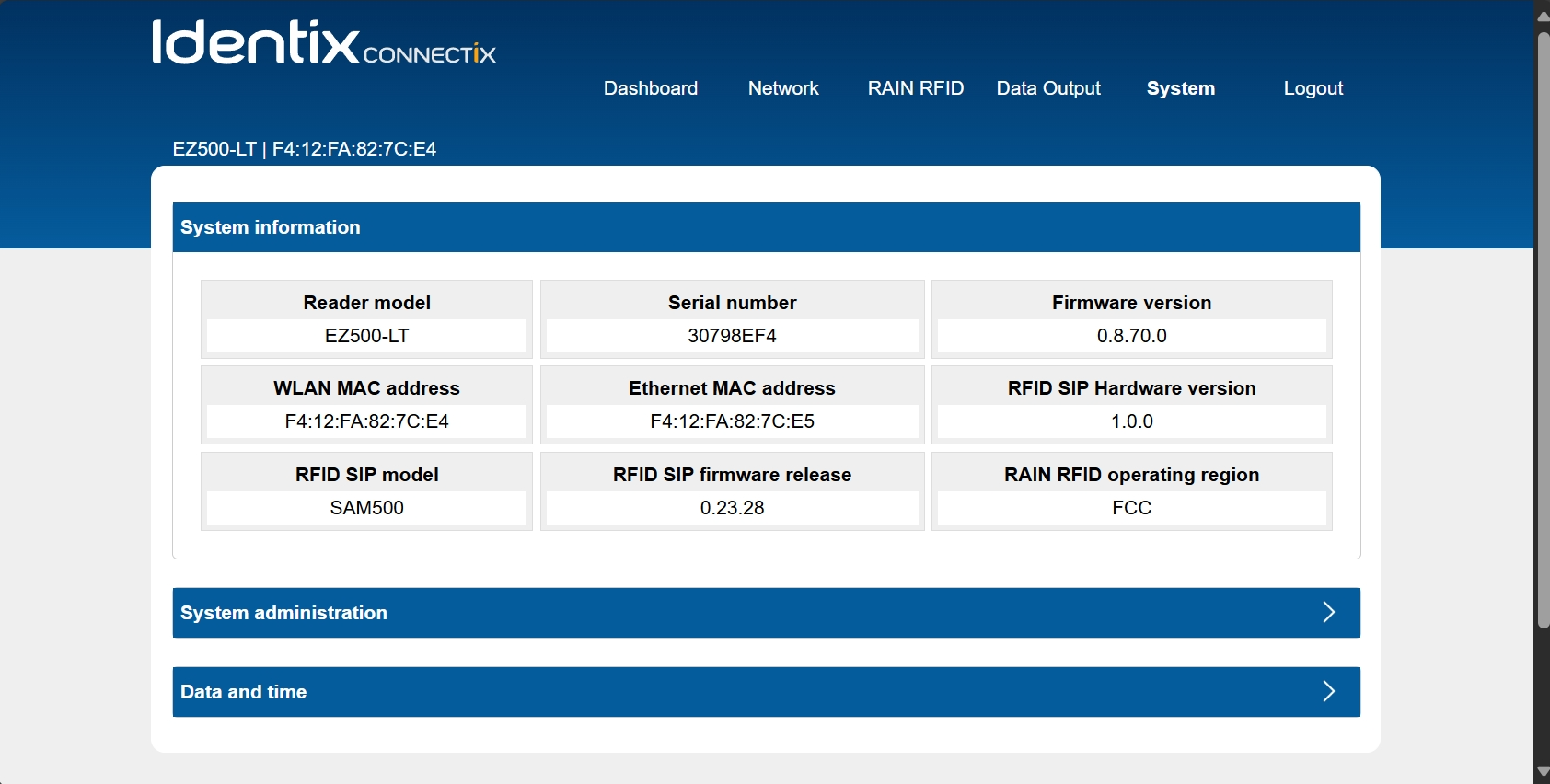
Shows the installed firmware version, MAC addresses, serial number, and other device details.
System administration
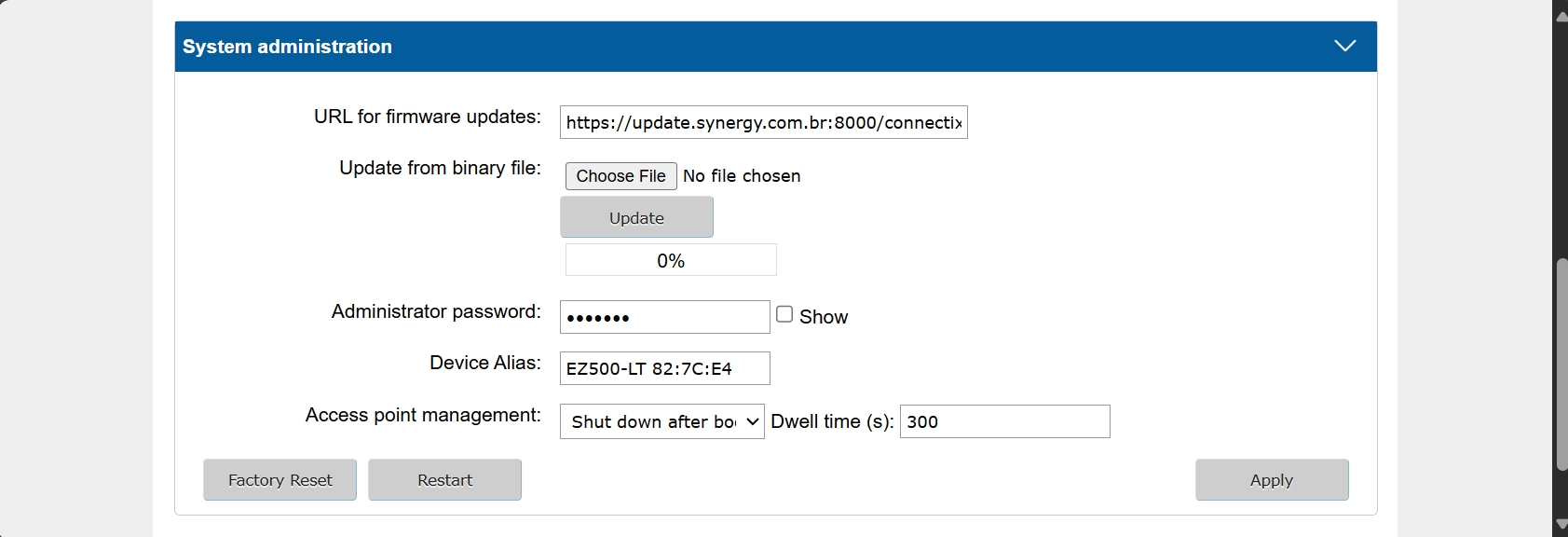
Section titled “System administration”You can:
- Update the device firmware.
- Change the administration password.
- Disable the configuration access point. The internal management hotspot shuts down automatically after startup when this option is enabled.
- Restore the device to factory settings.
Date and time
Section titled “Date and time”Set the NTP servers the reader uses to sync the date and time when it starts.
System date and time
Section titled “System date and time”Set the date and time manually here.

Contact
Section titled “Contact”For technical support, contact support@idntx.com.