Installing the 90C4090 and 85DL4090 Wide-Beam Antennas
The 90C4090 (circular) and the 85DL4090 (dual linear) are 40° x 90° fan-beam panels with an electrical tilt: the beam leaves the panel already leaning toward one end. This guide shows how to find that end, how to mount the antennas in a ceiling or on side walls, and how they are aimed inside the GateView OTP. It also covers the GateView OTP-7070, which uses 85C7070 antennas.
For use cases and a comparison with the 65C6095, see Wide-beam antennas in transition zones on idntx.com.
Find the tilt direction
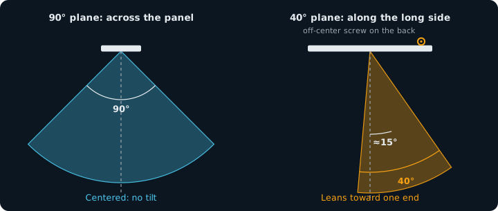
Section titled “Find the tilt direction”In the 90C4090 and the 85DL4090 the radiating elements are fed with a growing phase delay from one end of the panel to the other. The beam leans toward one end even with the panel flat on the wall. The tilt happens only in the 40° plane, along the long side. In the 90° plane, across the panel, the beam stays centered.
- 90C4090: 14° at 915 MHz, the middle of its 900-930 MHz band.
- 85DL4090: 15° on port 1 and 14° on port 2, at 915 MHz.
- On the back of both, a screw that sits on one end and not on the other marks the end the beam leans to.
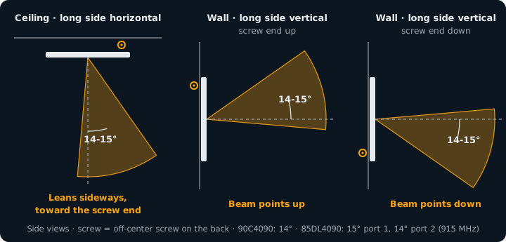
- Mount with the long side horizontal and the beam leans left or right, not down. Mount with the long side vertical and it leans up or down.
Which way it leans
Section titled “Which way it leans”The beam always leans toward the end of the panel that has the off-center screw on the back. Turn that end to where you want the beam to point:
| How the panel is mounted | Where the beam points | 90C4090 | 85DL4090 |
|---|---|---|---|
| Long side horizontal (ceiling or wall) | Sideways, toward the screw end | 14° | 15° port 1, 14° port 2 |
| Long side vertical, screw end up | Up, above the line straight out of the face | 14° up | 15° up (port 1), 14° up (port 2) |
| Long side vertical, screw end down | Down, below the line straight out of the face | 14° down | 15° down (port 1), 14° down (port 2) |
Angles at 915 MHz, measured from the line straight out of the face of the panel.
85DL4090 ports and polarization
Section titled “85DL4090 ports and polarization”The 85DL4090 has two SMA ports, one per polarization: one connector in the middle of each long side of the panel. The tilt screw tells them apart. Look at the back of the panel with the tilt screw on your left: port 1 is the connector on the top long side, port 2 the one on the bottom long side.
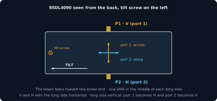
Each port feeds the same three patches, from a different edge:
| Port 1 | Port 2 | |
|---|---|---|
| Polarization, long side horizontal | Vertical (V) | Horizontal (H) |
| Polarization, long side vertical | Horizontal (H) | Vertical (V) |
| Gain @ 915 MHz | 8.5 dBiL | 8.0 dBiL |
| Beam @ 915 MHz (40° plane x 90° plane) | 38.7° x 89.9° | 41° x 96° |
| Electrical tilt @ 915 MHz | 15° | 14° |
- Port 1 is polarized across the long side of the panel, port 2 along it. Mount the panel the other way round and the two swap between V and H.
- The two ports are isolated by more than 12.5 dB across 900-930 MHz. Read them one after the other, never at the same time.
- A tag lying across the long side of the panel is read by port 1; a tag lying along it by port 2. With both ports on, any tag in the plane of the panel is read.
- Port 1 is the connector with no capacitor beside it on the board. Port 2 is the one with the small tuning capacitor next to it.
Tell the ports apart on site
Section titled “Tell the ports apart on site”The tilt screw is the quickest way. To double-check a panel that arrived without the P1 and P2 labels, use a tag before you mount it:
- Connect one port to the reader. Leave the other port unconnected.
- Hold a tag about 1 m in front of the panel with the tag lying across the long side of the panel, then turn it 90° so it lies along the long side.
- If the tag reads better lying across the long side, that connector is port 1 (
P1 · V). If it reads better lying along the long side, it is port 2 (P2 · H). - Label both connectors before the panel goes up.
Label the ports and cables
Section titled “Label the ports and cables”The two SMA connectors look the same from outside. Label them on the bench, before the panel goes up:
| Where | Label | Meaning |
|---|---|---|
| Next to the port 1 connector | P1 · V |
Port 1, vertical with the long side horizontal |
| Next to the port 2 connector | P2 · H |
Port 2, horizontal with the long side horizontal |
| Back of the panel, at the end marked by the off-center screw | TILT → |
The end the beam leans to |
| Reader end of each cable | A1, A2, B1, B2 |
Antenna (A or B) and antenna port (1 or 2) |
With the long side vertical, V and H swap: the port number stays, so read the label by its number.
Install in the ceiling
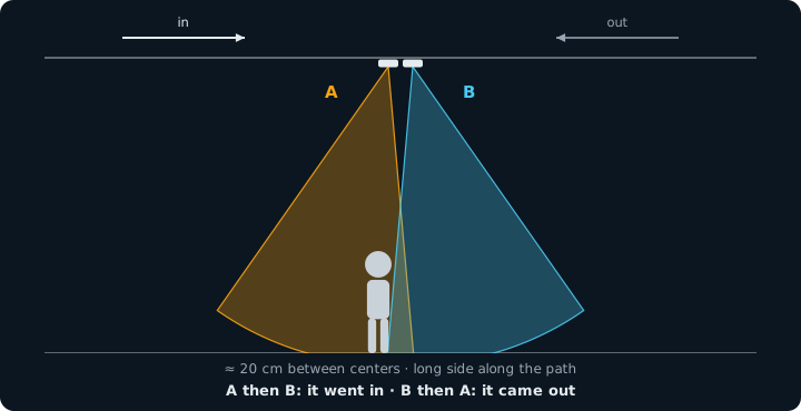
Section titled “Install in the ceiling”This is the layout for a passage with direction: two antennas back to back above the line people and goods cross.
- Lay the long side of each panel along the direction of travel. The 90° plane then runs across the passage.
- Turn the two panels so their tilts point to opposite sides, using the off-center screw on the back: antenna A toward the approach, antenna B toward the exit.
- Keep about 20 cm between the centers of the two antennas.
- The face of the panel points to the floor. Keep metal ducts, lamps and beams away from the front of it.
- Run the cables to the reader. The 90C4090 uses one reader port. The 85DL4090 uses two, one per polarization: put its port 1 and port 2 on two reader ports in that order, so the software knows which polarization read each tag.
- Name the reader ports A and B in the software. The order of the reads gives the direction.
Install on the side walls
Section titled “Install on the side walls”For a wider corridor, or when the ceiling is too high, put the antennas on the walls or on posts on both sides of the passage.
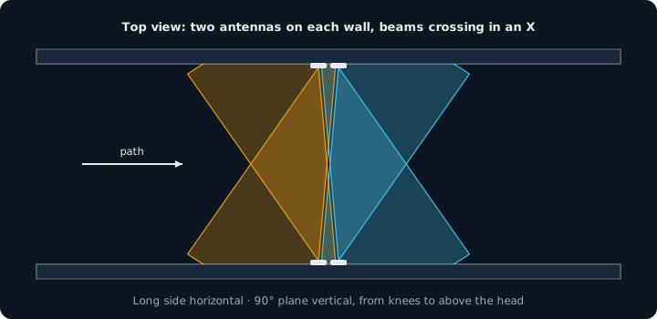
- Long side horizontal, along the direction of travel. The 90° plane is vertical and covers from the knees to above the head.
- Two antennas on each side, about 20 cm apart, with tilts pointing to opposite sides. The beams of the two walls cross in an X in the middle.
- Mount the panels at the height where the tags pass.
- Four 90C4090 use four reader ports. Four 85DL4090 use eight: plan the reader or an RF splitter.
GateView OTP
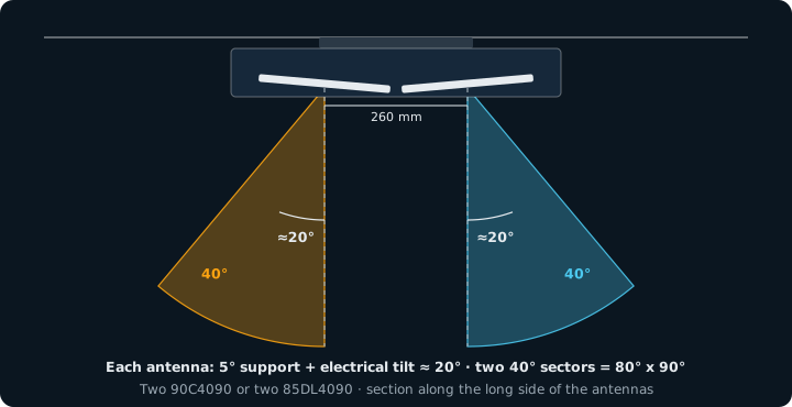
Section titled “GateView OTP”The GateView OTP always comes with two antennas inside: two 90C4090 (circular) or two 85DL4090 (dual linear). They sit 260 mm apart, each on a support tilted 5°, in opposite directions along the long side. The 5° of the support add to the electrical tilt, so each sector points about 20° to one side. Two 40° sectors side by side give the 80° x 90° opening of the portal.
- The ceiling bracket runs parallel to the long side of the antennas. Install it along the direction of travel to get the two sectors in sequence, one before and one after the line, and read the direction.
- Install it across the direction of travel to spread the 80° over a wide gate.
- With 90C4090 the portal uses two reader ports. With 85DL4090 it uses four, which fills a four-port reader such as the EZ700 or EZ500: reader ports 1 and 2 go to ports 1 and 2 of antenna A, reader ports 3 and 4 to ports 1 and 2 of antenna B.
- In the GateView OTP the long side of the antennas runs along the passage. Port 1 is then polarized across the passage and port 2 along it.
GateView OTP-7070
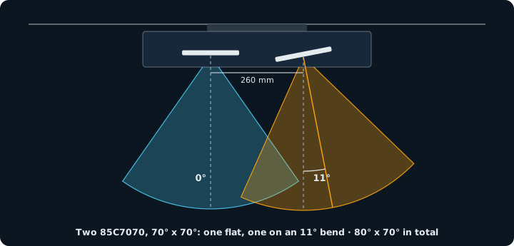
Section titled “GateView OTP-7070”The OTP-7070 uses two 85C7070 antennas, 70° x 70° and circular, with no electrical tilt. They also sit 260 mm apart. One lies flat and points straight at the floor. The other sits on a bend of 11° and points to the outer side. The two 70° x 70° sectors add up to an 80° x 70° opening, wider toward that side, for open areas and gates where the read zone does not need to be narrow.
- Point the side with the tilted antenna toward the area you want to reach farther.
- Each 85C7070 uses one reader port. The cabinet has room for two more antennas.
Size of the read zone on the floor
Section titled “Size of the read zone on the floor”A first estimate, from the angles alone: the edge of each beam where the signal drops by half (-3 dB), drawn down to the height where the tags pass. Real reach also depends on reader power, tag and surroundings, so confirm on site.
| Antennas at | Tags at | One 90C4090 or 85DL4090, flat in the ceiling | GateView OTP |
|---|---|---|---|
| 2.5 m | 1.0 m | 1.2 x 3.0 m | 2.5 x 3.0 m |
| 3.0 m | 1.0 m | 1.6 x 4.0 m | 3.4 x 4.0 m |
| 3.5 m | 1.0 m | 2.0 x 5.0 m | 4.2 x 5.0 m |
Length along the long side of the antennas x width across it. Tilt taken as 15°, GateView OTP sectors at ±20°.
Before you switch it on
Section titled “Before you switch it on”- Start at low power and raise it step by step until the tags at the edge of the zone read every time.
- Test with the real item and the real tag, at the real speed of the passage.
- Walk a tag along the shelves next to the zone. If it reads, lower the power or turn the panel.
- Write down the antenna, port and angle of each point. It saves time at the next visit.
Questions
Section titled “Questions”Is the tilt a downtilt?
Only if you mount the panel with its long side vertical. The tilt follows the long side of the panel, so with the long side horizontal the beam leans sideways.
Can I cancel the tilt?
Yes, by tilting the panel the other way with an articulated support. The GateView OTP does the opposite: its supports add 5° to the electrical tilt.
90C4090 or 85DL4090?
Same body and same fan. Pick the 90C4090 when tags pass in any rotation and you want one cable per antenna. Pick the 85DL4090 when you want more reach in each polarization and have two reader ports per antenna.